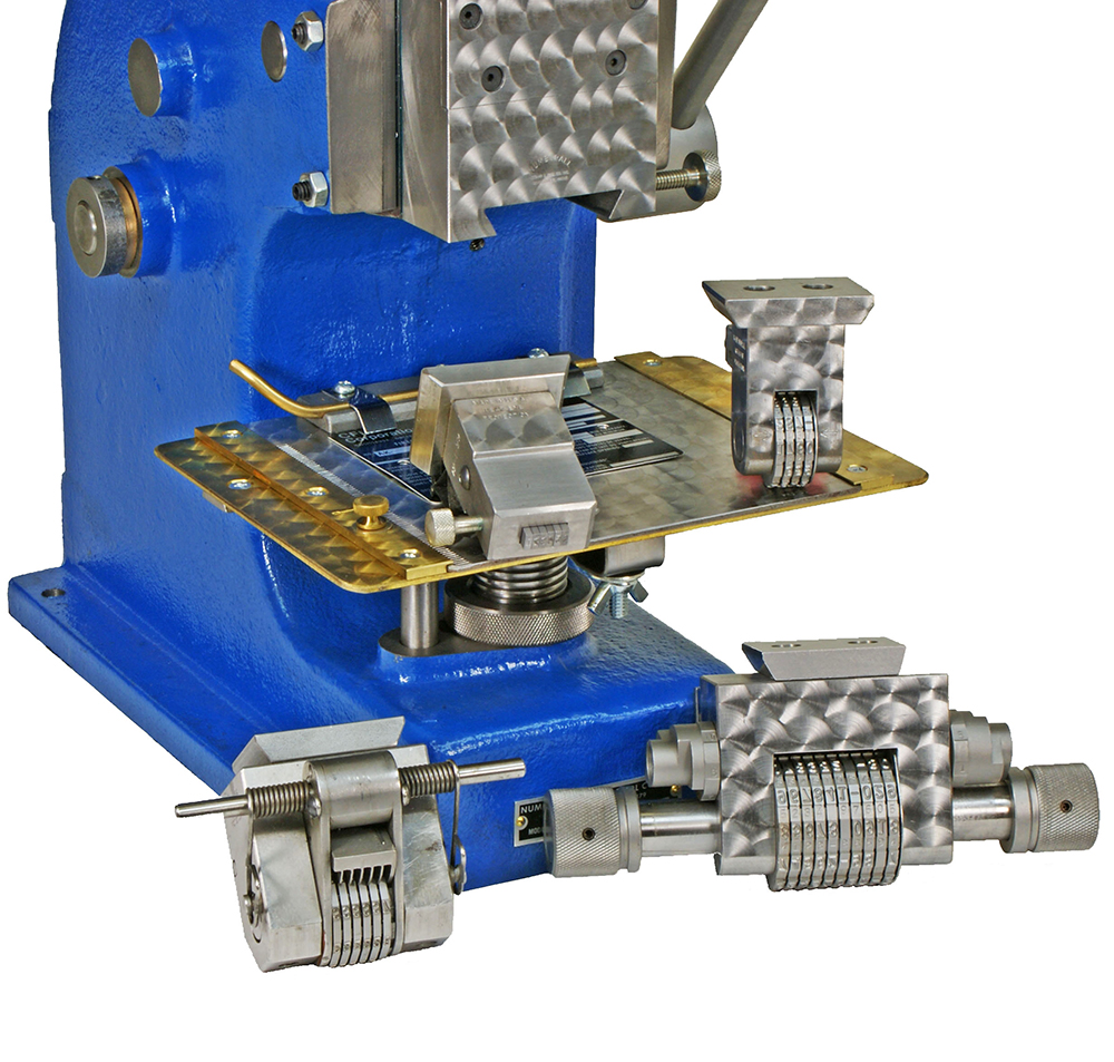
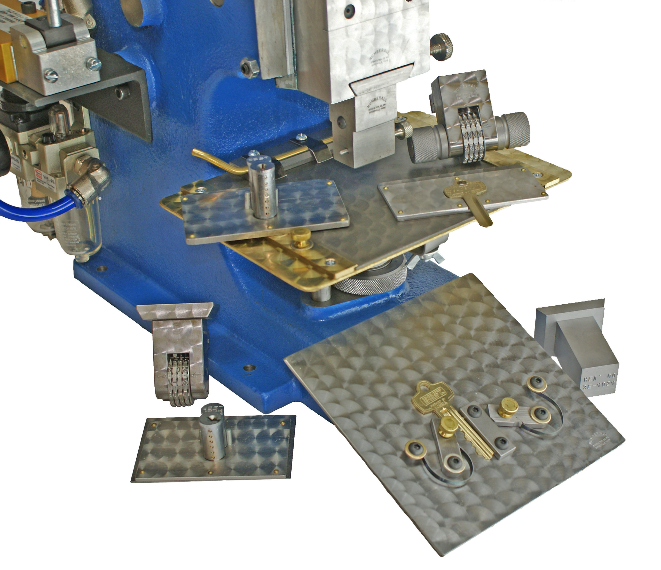
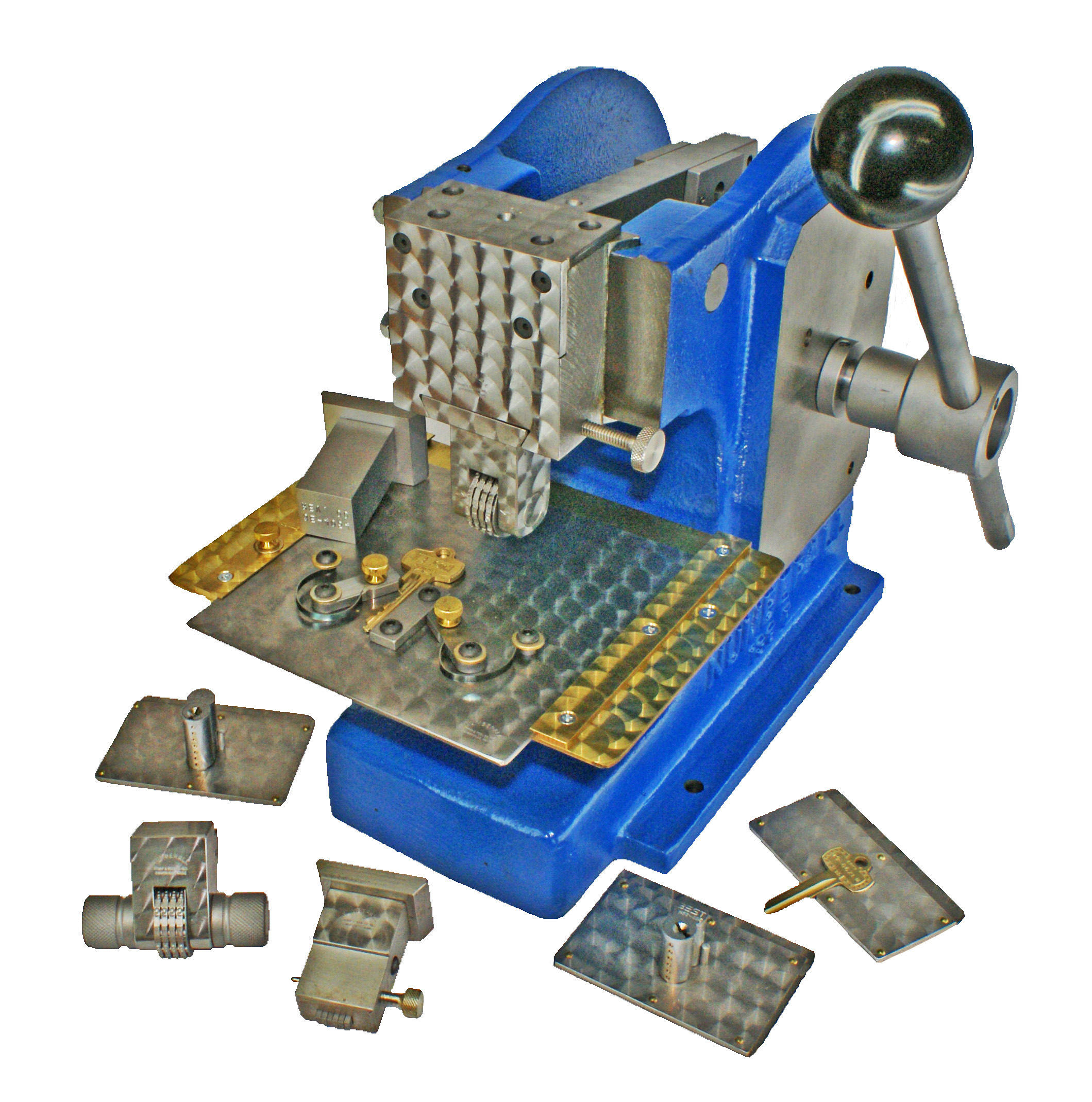
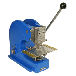
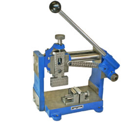
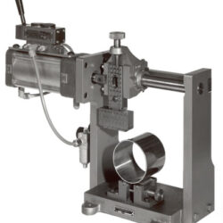
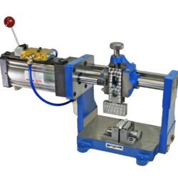
Model 136 Hand-Operated Bench Top Press
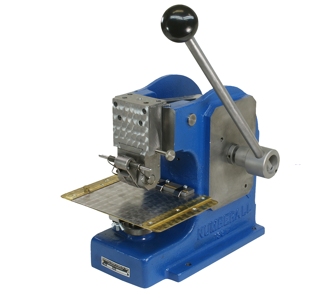
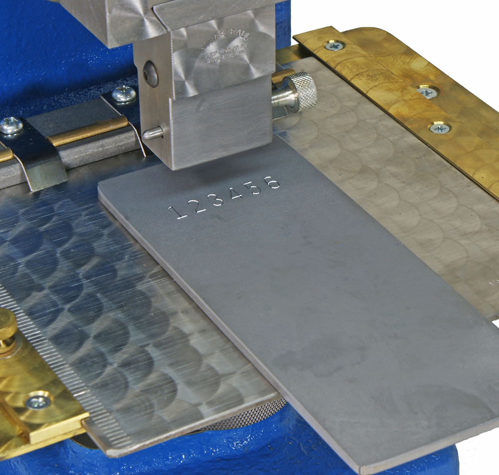
Numberall manufactures a variety of economical bench-top presses. Bench-top mounting saves valuable floor space. The Model 136 is our hand operated bench top press. These presses are designed to work in conjunction with our numbering machines for marking name plates and thin parts.
- Durable Construction
- Backed By Lifetime Guarantee
- Tailored to Fit Your Needs
| Weight | 65 lbs |
|---|---|
| Dimensions | 14 × 11 × 20 in |
| Optional Equipment | Adjustable Table |
| Throat Depth | 2-1/2" |
| Vertical Table Adjustment | 2" |
| Ram & Table Clearance | 3-3/4" |
Call For Quote
Quote Requirements
- Part Material (Steel, Aluminum, etc)
- Part Thickness
- Number of Characters to Stamp
- Character Size (inches)
- Access to Air or Electricity
Prefer to email a quote request?
Product Resources
Catalog Request
Product Manual (PDF)
Length of Impression Ruler (PDF)
Numberall manufactures a variety of economical bench-top presses. Bench-top mounting saves valuable floor space and keeps larger presses free for other work. The bench top presses are available in Hand-Operated (Model 136), Air-Operated (Model 136A), and Motorized (Model 137) versions. These presses are compact and easily mounted on a workbench. They are designed for marking name plates and other flat objects.
Operation
- The Model 136 is hand-operated.
- By manually pulling the lever, a cam is rotated to create the stamping force. This adjusts the table so that when the cam rotates to high cam position, minimal effort is required to mark the part.
- The Model 136A uses an air-cylinder to generate its power.
- A hand-operated lever valve is pulled toward the operator. This causes the ram to move down to stamp the part.
- Once stamped, the lever valve is released and the ram then moves to the home position.
- The Model 136A is a very simple, low maintenance press with very few moving parts. In fact, we do not recommend any spare parts for this machine.
- The Model 136A can also be adjusted so that any part thickness within the stroke range can be stamped without height adjustment. By simply adjusting the air pressure, the press will stamp to a certain depth.
- Essentially, the press will “stall out,” but not damage the part or press components because the air pressure is lower than standard.
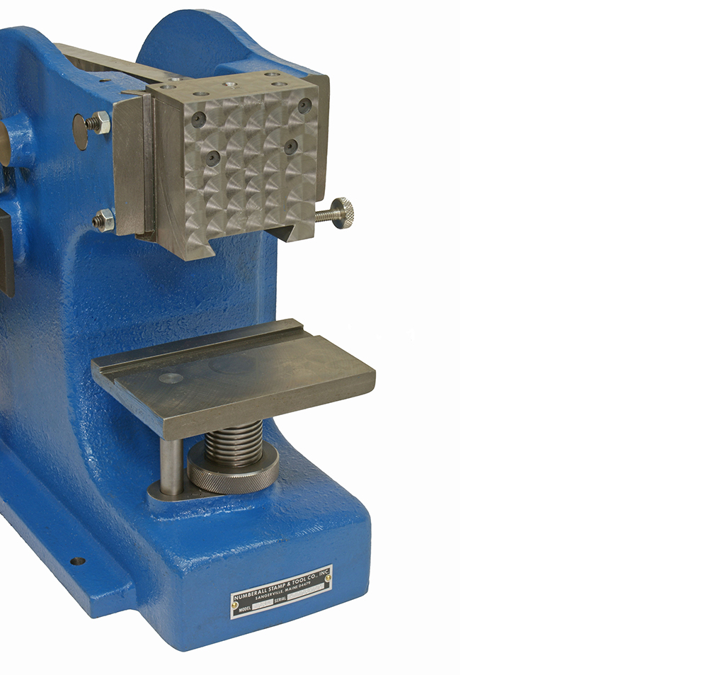
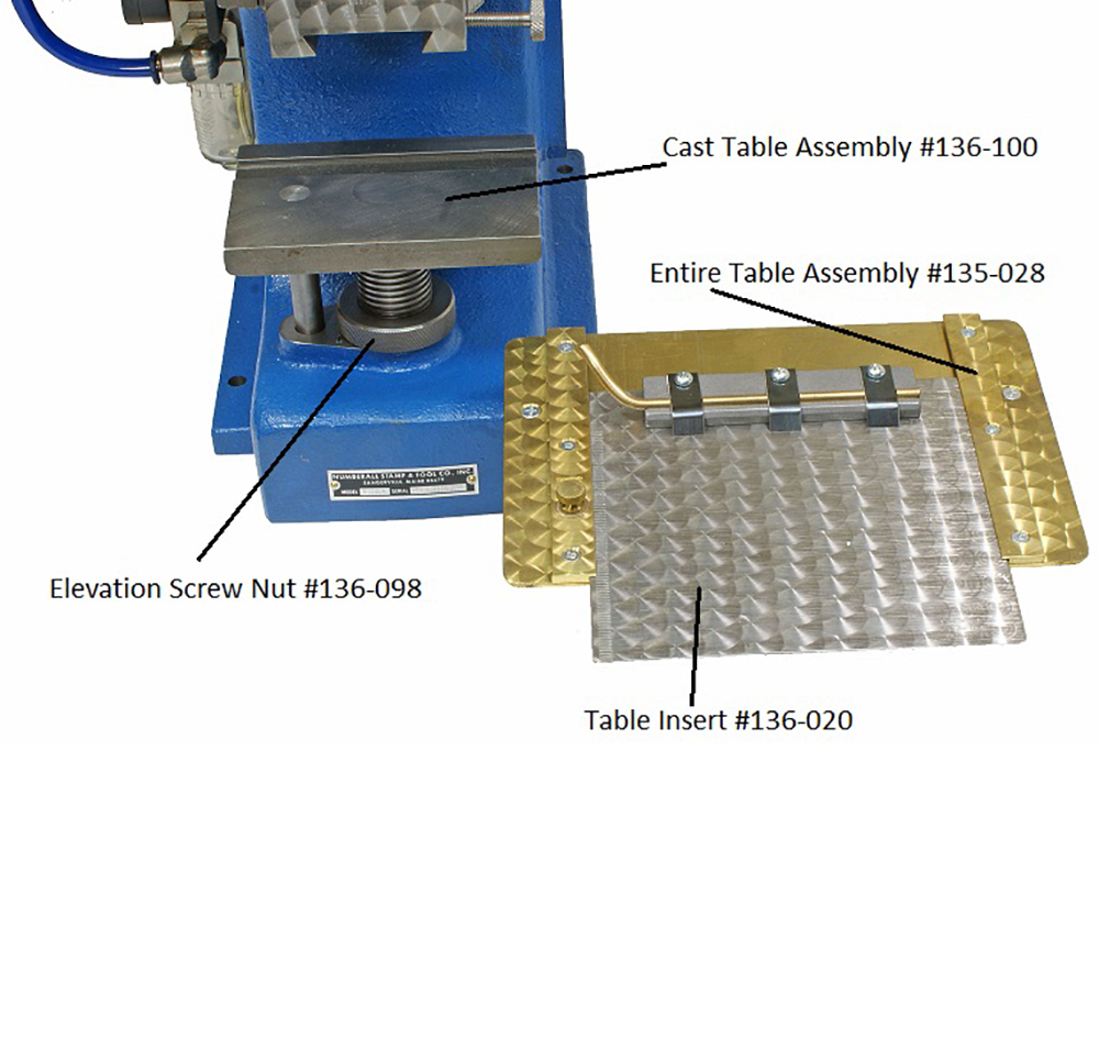
- An acme screw and nut, attached below the cast table, regulates depth of stamping.
- A separate guiding rod helps align the table. By turning the acme nut you can raise or lower the table for depth adjustment.
- The presses feature a short, safe 3/16” stroke, negating the need for external guarding.
- The Model 136A can be equipped with an optional two-hand trip.
- Numberall’s standard dovetail shank allows quick changing of marking devices. The same dovetail is used in all of our presses as well as the Model 116 Dovetail Adapter.
Construction & Parts
The Models 136, 136A, and 137 use the same base casting.
- Numberall's presses have cast iron "C" frames for distortion-free stamping with a smooth, static non-impact marking force.
- No die cast parts are used. Many imported presses are made using round column construction with a spring release marking force, which may result in a harsh impact shock.
- The large quick-change dovetail ram evenly distributes the marking force across the marking device frame with minimal stress.
- Clearances and pressures are the same for all models.
Character Capacity Chart
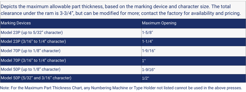
Maximum Part Thickness Chart
Compatibility
- A variety of marking devices can be installed in the presses, depending on part thickness and character capacity requirements.
Options
- Tripping Attachment (for use with the Model 50P only)
- Adjustable Table (for in-out and left-right movement of table)
- Filter, Lubricator, Regulator, & Gauge (FLR&G) (for Model 131A only)
- Model 113 Strip Holder
- Universal Key Nest
- Custom Nest
Product Specs
Additional information
| Weight | 65 lbs |
|---|---|
| Dimensions | 14 × 11 × 20 in |
| Optional Equipment | Adjustable Table |
| Throat Depth | 2-1/2" |
| Vertical Table Adjustment | 2" |
| Ram & Table Clearance | 3-3/4" |
Please fill out this form to request a quote and our sales engineers will review promptly and reply asap.

